
P8 and P9 connector
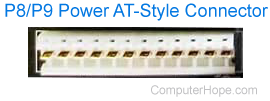
Alternatively called the AT-style connector, P8 connector, and P9 connector, the P8 and P9 are IBM power connectors. They connect the power supply to the motherboard on AT (advanced technology), Baby AT, and LPX (low profile extension) motherboards. The picture shows this connector. With the introduction of ATX (advanced technology extended), motherboards and power supplies were replaced by the ATX-style connector.
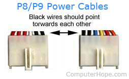
One of the most difficult and troublesome parts of this connector was that the P8 and P9 connectors looked identical. Although these connections were keyed, it was still possible to put the P8 connector into the P9 port on the motherboard or visa-versa. Doing so would physically damage the motherboard. When working with this connector, ensure the black cables point into each other, as shown in the picture below.
Finally, the pinout descriptions for the P8 and P9 power connectors are below.
| Pin | Color | Function | Connector |
|---|---|---|---|
| 1 | Orange | "Power Good" | P8-1 |
| 2 | Red (XT No Wire) | +5V DC | P8-2 |
| 3 | Yellow | +12V DC | P8-3 |
| 4 | Blue | -12V DC | P8-4 |
| 5 | Black | Ground | P8-5 |
| 6 | Black | Ground | P8-6 |
| 7 | Black | Ground | P9-1 |
| 8 | Black | Ground | P9-2 |
| 9 | White | -5V DC | P9-3 |
| 10 | Red | +5V DC | P9-4 |
| 11 | Red | +5V DC | P9-5 |
| 12 | Red | +5V DC | P9-6 |