
System panel connector
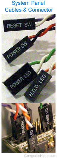
Alternatively called the fpanel or front panel connector, the system panel connector or system panel header controls a computer power button, reset button, and LED's (light-emitting diode). The System panel cables, as shown in the picture are two wire cables that are color-coded to help identify where they connect to the motherboard system panel connector. The black or white wire is the GND (ground) wire and the colored wire is the powered wire. The cables, colors, and connections vary depending on the computer case and motherboard you have, however, generally include the cables mentioned below.
Types of system panel cables
Cables containing "SW" are for a case switch and "LED" or for the case lights.
- HDD LED (IDE LED) - The LED activity light for the hard disk drive. This indicator is the light that flashes as information is being written to and read from the hard drive. If an older computer, this cable may be labeled IDE LED for the IDE (integrated drive electronics) interface.
- PLED (Power LED) - The LED power light, which indicates when the computer is on, off, or in Standby.
- PWRSW (Power SW) - Controls the power button (power switch) that lets you turn on and off the computer.
- Reset SW - Handles the reset button to restart the computer.
- Speaker - The internal speaker used to sound the beep noises you hear from your computer when it is booting.
With most computer motherboards, the system panel cables are connected directly to the motherboard. However, some motherboard manufacturers such as ASUS include a Q-Connector with the motherboard. With a Q-Connector, the user can connect the system panel cables away from the motherboard and then connect the Q-Connector to the motherboard.
Which direction do the system panel cables connect?
The system panel cables are not keyed so can be plugged in any direction. Except for the LED cables, the system panel connector cables can be plugged in any direction. If the LED cables are plugged in backward, the LED light will not work. Usually, with most modern motherboards, you can identify what cable goes where by looking at the motherboard for a + and a - symbol. The colored wire (powered wire) would connect to the + symbol and a white or black cable (ground) would connect to the - symbol.
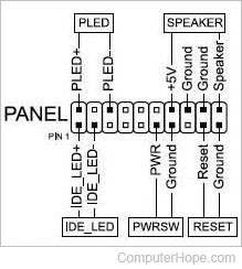
In the diagram example above, copied from a motherboard manual, you can see how each of these cables connects to the motherboard. For example, in the top-left portion for the PLED (Power LED), the first pin is PLED+, indicating the colored wire side should connect to it. Remember, how these cables connect varies depending on your motherboard.
Bezel, Computer abbreviations, Motherboard, Motherboard terms