
Floppy cable
A floppy cable is a ribbon cable found in PCs that allows one or more floppy disk drives to connect to a computer. The illustration shows is a visual example of what a floppy cable may look like and where each end of the connectors connect. This cable allows a desktop computer to have two floppy drives connected to one floppy controller.


Because floppy drives don't have a primary or secondary jumper, the drives are defined by cable select, which is identified by looking for the cable twist. Like an IDE (integrated drive electronics) cable, most floppy cables have a red strip along one side of the ribbon cable to indicate pin 1. Today, if any floppy drive is in the computer, it connects to "Drive A:" and the end cable connected to the motherboard.
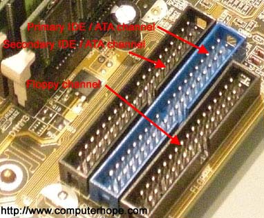
The floppy channel, FDD (floppy disk drive) header, or floppy connection is where the floppy drive connects to the computer motherboard. The picture below shows a motherboard with two IDE connections and a floppy channel connector.
Finally, the standard PC floppy drive connector contains 34 pin holes. Below is a listing of each of these pins and their descriptions.
| Pin | Description |
|---|---|
| Pin 1 | Ground |
| Pin 2 | Unused |
| Pin 3 | Ground |
| Pin 4 | Unused |
| Pin 5 | Ground |
| Pin 6 | Unused |
| Pin 7 | Ground |
| Pin 8 | Index |
| Pin 9 | Ground |
| Pin 10 | Motor Enable A |
| Pin 11 | Ground |
| Pin 12 | Drive Select B |
| Pin 13 | Ground |
| Pin 14 | Drive Select A |
| Pin 15 | Ground |
| Pin 16 | Motor Enable B |
| Pin 17 | Ground |
| Pin 18 | Direction (Stepper Motor) |
| Pin 19 | Ground |
| Pin 20 | Step Pulse |
| Pin 21 | Ground |
| Pin 22 | Write Data |
| Pin 23 | Ground |
| Pin 24 | Write Enable |
| Pin 25 | Ground |
| Pin 26 | Track 0 |
| Pin 27 | Ground |
| Pin 28 | Write Protect |
| Pin 29 | Ground |
| Pin 30 | Read Data |
| Pin 31 | Ground |
| Pin 32 | Select Head 1 |
| Pin 33 | Ground |
| Pin 34 | Ground |
Floppy disk drive, Floppy diskette, Floppy drive terms, IDE cable