
Logical operation
A logical operation is a special symbol or word that connects two or more phrases of information. It is used to test whether a certain relationship between the phrases is true or false.
In computing, logical operations are necessary because they model the way that information flows through electrical circuits, such as those inside a CPU (Central Processing Unit). These types of operations are called boolean operations.
The elements in a circuit which behave according to Boolean logic are called logic gates.
Fundamental logic operations
The following seven logic operations take inputs that are either true (1) or false (0) and produce a single output value that is also true or false.
Most of these operations can take more than two inputs, except for the NOT operation which takes only one input. Below are examples using only one or two inputs, which is what usually happens inside a computer.
The operations are listed below. Click a link for an operation to learn more.
AND
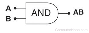
The AND logic operation returns true only if either of its inputs are true. If either of the inputs is false, the output is also false.
In computer programming, the AND operation is usually written as && (two ampersands).
In Boolean algebra, the AND operation of two inputs A and B can be written as AB.
Below is the truth table for an AND operation, and the circuit diagram of an AND logic gate.
| AND | ||
|---|---|---|
A |
B |
AB |
| 0 | 0 | 0 |
| 1 | 0 | 0 |
| 0 | 1 | 0 |
| 1 | 1 | 1 |
OR
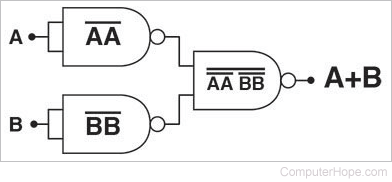
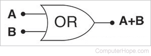
The OR logic operation returns true if either of its inputs are true. If all inputs are false, the output is also false.
In computer programming, the OR operation is usually written as || (two vertical bars).
In Boolean algebra, the OR value of two inputs A and B can be written as A+B.
Do not mistake the OR operation for arithmetic addition, even though they both use the "+" symbol. They are distinct operations.
Below is the truth table for an OR operation, and the circuit diagram of an OR logic gate.
| OR | ||
|---|---|---|
A |
B |
A+B |
| 0 | 0 | 0 |
| 1 | 0 | 1 |
| 0 | 1 | 1 |
| 1 | 1 | 1 |
NOT
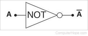
The NOT logic operation returns true if its input is false, and false if its input is true.
In computer programming, the NOT operation is usually written as ! (an exclamation mark).
In Boolean algebra, the NOT value of an input A can be written as A̅ (A with an overscore).
Below is the truth table for a NOT operation, and the circuit diagram of a NOT logic gate.
| NOT | |
|---|---|
A |
A̅ |
| 0 | 1 |
| 1 | 0 |
NAND
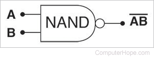
The NAND logic operation (which stands for "NOT AND") returns true if its inputs are false, and false if either of its inputs is true.
NAND Flash is a type of flash memory based on NAND logic gates.
In Boolean algebra, the NAND value of two inputs A and B can be written as ![]() (AB with an overscore).
(AB with an overscore).
NAND has the distinction of being one of two "universal" logic gates because any other logic operation can be created using only NAND gates. (The other universal logic gate is NOR.)
Below is the truth table for a NAND operation, and the circuit diagram of a NAND logic gate.
| NAND | ||
|---|---|---|
A |
B |
___ AB |
| 0 | 0 | 1 |
| 1 | 0 | 1 |
| 0 | 1 | 1 |
| 1 | 1 | 0 |
NOR
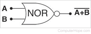
The NOR logic operation (which stands for "NOT OR") returns true if its inputs are false, and false if either of its inputs is true.
NOR Flash is a type of flash memory based on NOR logic gates.
In Boolean algebra, the NOR value of two inputs A and B can be written as ![]() (A+B with an overscore).
(A+B with an overscore).
NOR has the distinction of being one of two "universal" logic gates, because any other logic operation can be created using only NOR gates. (The other universal logic gate is NAND.)
Below is the truth table for a NOR operation, and the circuit diagram of a NOR logic gate.
| NOR | ||
|---|---|---|
A |
B |
_____ A+B |
| 0 | 0 | 1 |
| 1 | 0 | 0 |
| 0 | 1 | 0 |
| 1 | 1 | 0 |
XOR
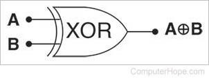
The XOR logic operation (which stands for "Exclusive OR" returns true if either of its inputs differ, and false if they are all the same. In other words, if its inputs are a combination of true and false, the output of XOR is true. If its inputs are all true or all false, the output of XOR is false.
In Boolean algebra, the XOR value of two inputs A and B can be written as A⊕B (the XOR symbol, ⊕, resembles a plus sign inside a circle).
Below is the truth table for an XOR operation, and its circuit diagram.
| XOR | ||
|---|---|---|
A |
B |
A⊕B |
| 0 | 0 | 0 |
| 1 | 0 | 1 |
| 0 | 1 | 1 |
| 1 | 1 | 0 |
XNOR
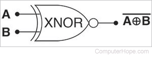
The XNOR logic operation (which stands for "Exclusive NOT OR" returns true if either of its inputs are the same, and false if either of them differ. In other words, if its inputs are a combination of true and false, the output of XNOR is false. If its inputs are all true or all false, the output of XNOR is true.
In Boolean algebra, the XNOR value of two inputs A and B can be written as ![]() (the XOR symbol, ⊕, resembles a plus sign inside a circle with line over everything).
(the XOR symbol, ⊕, resembles a plus sign inside a circle with line over everything).
Below is the truth table for an XNOR operation, and its circuit diagram.
| XNOR | ||
|---|---|---|
A |
B |
_____ A⊕B |
| 0 | 0 | 1 |
| 1 | 0 | 0 |
| 0 | 1 | 0 |
| 1 | 1 | 1 |
Accumulator, Bitwise operator, Boolean, Idempotence, Operator, Programming terms, Pseudo-operation